CO.,LTD.")


Product Details
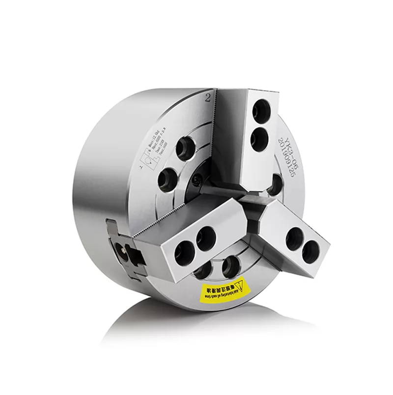
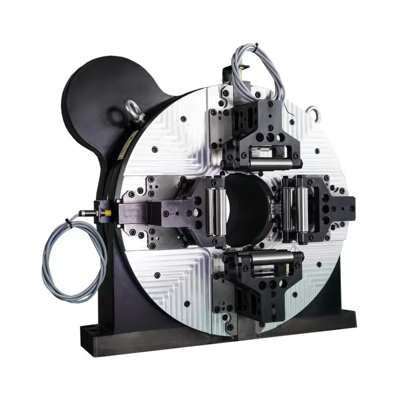
Traditional center rests are generally supported at two or three points.
Each support rod is manually adjusted to achieve concentricity with the spindle.
The accuracy of adjustment often depends on the feel of the skilled worker.
Therefore, this method has low accuracy and efficiency and cannot meet the high-precision requirements of CNC machine tools.
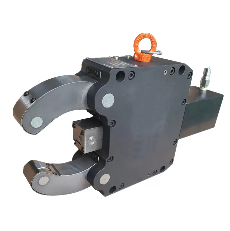
Therefore, the hydraulic self-centering center rest came into being.

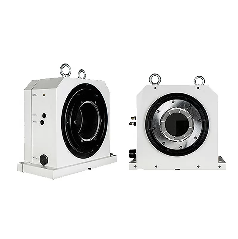
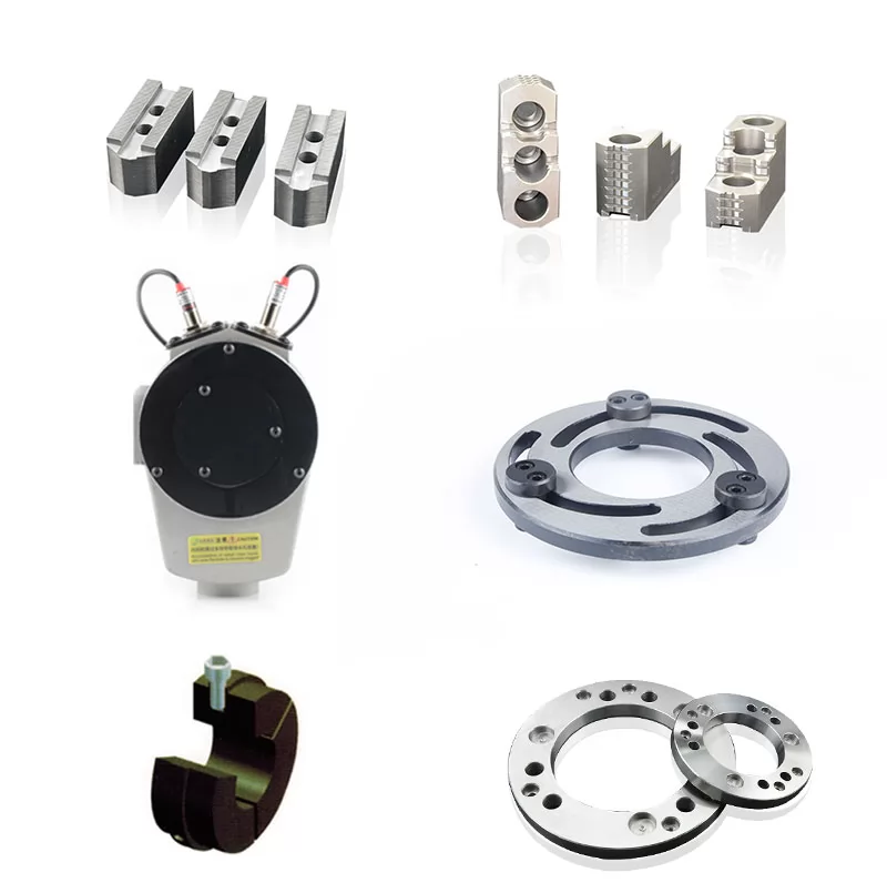
The structure of the hydraulic self-centering center frame includes a shell,
and both sides of the front end of the shell are rotatably connected to the clamping arms.
A cam push rod that performs linear reciprocating motion is also installed in the shell,
and both sides of the cam push rod are rotatably connected to the return plate.
There is a slide groove on the return plate, and a pin corresponding to
the slide groove is provided at the rear end of the clamping arm,
and the pin is installed in the slide groove; in addition,
a support bearing is also provided at the front end of the clamping arm,
and a support bearing is also provided at the front end of the cam push rod;
a rotatable sliding bearing is provided at the rear end of the clamping arm,
and a curved surface corresponding to the sliding bearing is provided on the cam push rod;
a hydraulic drive cylinder is provided at the rear end of the shell,
and the hydraulic drive cylinder includes a cylinder body and a hydraulic piston rod placed in the cylinder body for driving the cam push rod,
and the hydraulic piston rod is connected to the rear end of the cam push rod.
Product Size

Product Parameters
| HY-A series center stand specifications, dimensions and technical performance parameters | ||||||||||
| Model | HY65A | HY100A | HY150A | HY200A | HY260A | HY280A | HY310A | HY350A | HY420A | HY520A |
| Clamping diameter range | φ5-φ65 | φ10-φ100 | φ20-φ155 | φ30-φ200 | φ35-φ260 | φ40-φ280 | φ50-φ310 | φ70-φ350 | φ115-φ420 | φ150-φ520 |
| L1(mm) | 231 | 314 | 441 | 520 | 665 | 670 | 743 | 798 | 908 | 948 |
| L2(mm) | 54 | 68 | 104 | 125 | 157 | 161 | 177 | 229 | 258 | 278 |
| L3(mm) | 53 | 100 | 150 | 170 | 230 | 230 | 270 | 240 | 265 | 315 |
| L4(mm) | 94 | 110 | 148 | 175 | 208 | 208 | 228 | 235 | 260 | 290 |
| A1(mm) | 134 | 170 | 240 | 280 | 360 | 360 | 400 | 461 | 440/475 | 560/680 |
| A2(mm) | 150 | 188 | 265 | 310 | 392 | 392 | 442 | 449 | 510 | 750 |
| B1(mm) | 65 | 80 | 95 | 105 | 110 | 110 | 125 | 125 | 135 | 155 |
| B2(mm) | 32 | 40 | 45 | 55 | 60 | 60 | 75 | 75 | 75 | 95 |
| B3(mm) | 15 | 19 | 20 | 25 | 25 | 25 | 29 | 29 | 29 | 32 |
| φ1(mm) | 65 | 100 | 155 | 200 | 260 | 280 | 310 | 350 | 420 | 520 |
| φ2(mm) | 5 | 10 | 20 | 30 | 35 | 40 | 50 | 70 | 115 | 150 |
| φ3(mm) | 12 | 18 | 18 | 18 | 22 | 22 | 22 | 22 | 22 | 22 |
| D(mm) | 67 | 102 | 156 | 205 | 268 | 280 | 311 | 355 | 421 | 520 |
| Working Pressure (MPa) | 0.5-2.5 | 0.5-2.5 | 0.5-2.5 | 0.5-2.5 | 0.5-3 | 0.5-3 | 0.5-3.5 | 0.5-3.5 | 0.5-5 | 0.5-5 |
| Working Range Centering Accuracy | 0.02 | 0.05 | 0.04 | 0.05 | 0.05 | 0.06 | 0.06 | 0.06 | 0.07 | 0.08 |
| Repeat | 0.01 | 0.01 | 0.01 | 0.1 | 0.01 | 0.01 | 0.01 | 0.01 | 0.02 | 0.02 |
| Net Weight (kg) | 7 | 20 | 46 | 69 | 106 | 106 | 158 | 186 | 216 | 328 |


-

How to operate the Hydraulic Center Rest
Sep. 26, 2025
-

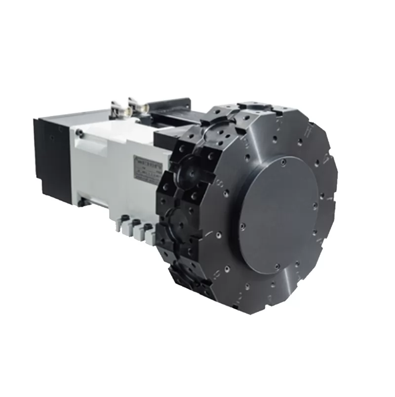
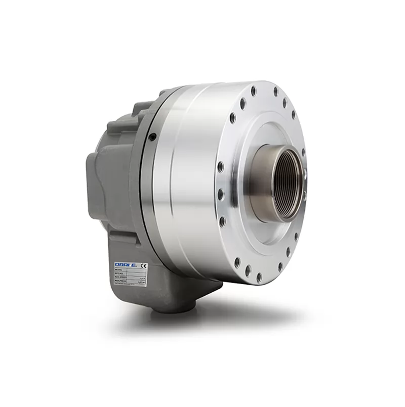
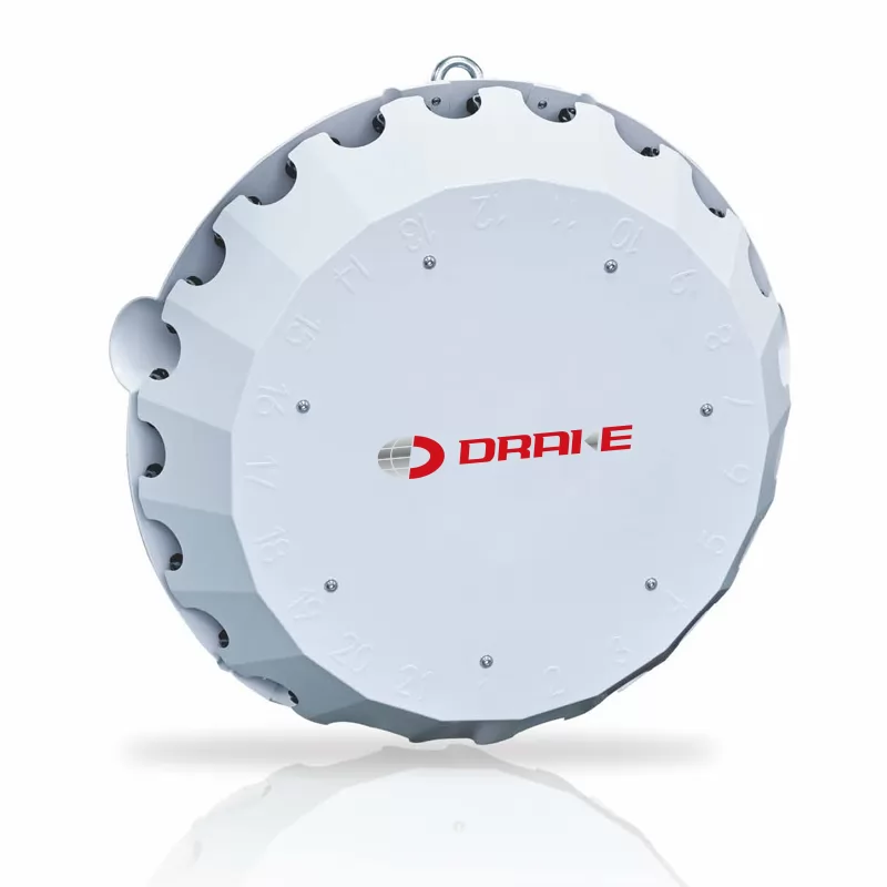
Selection and use of nc Turret
Sep. 26, 2025
-

What safety features does the Hydraulic Center Rest have?
Sep. 25, 2025
-

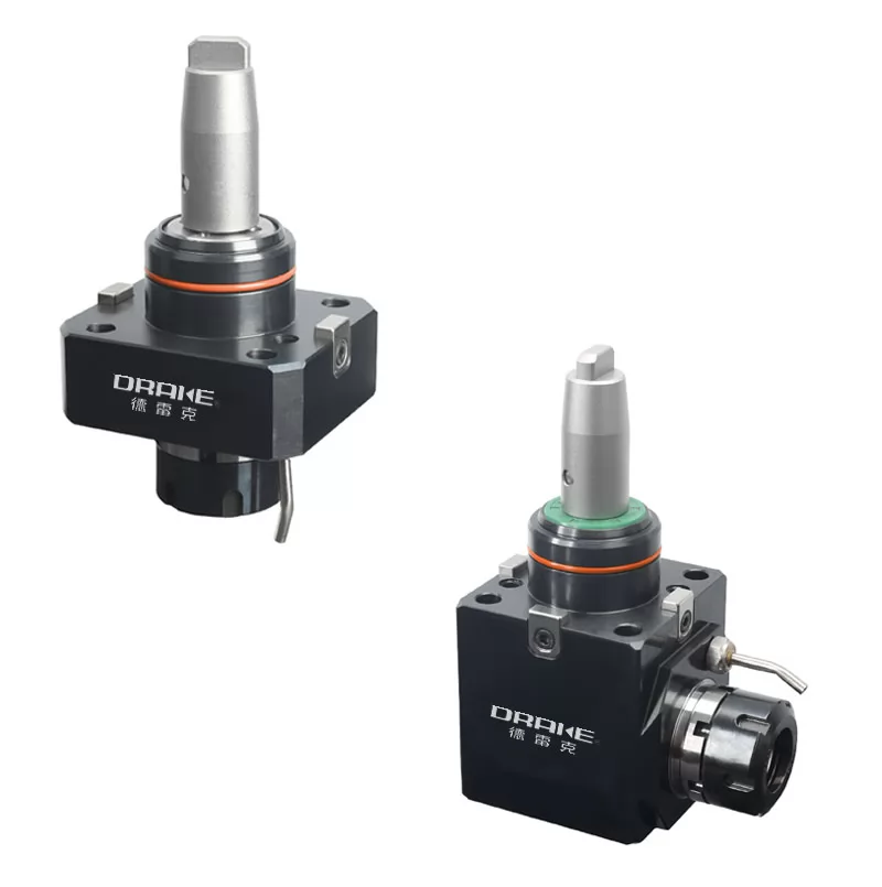
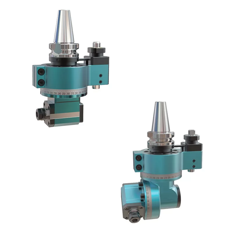
What are the characteristics of angle heads?
Sep. 25, 2025
-

How does the Hydraulic Center Rest usually operate?
Sep. 24, 2025